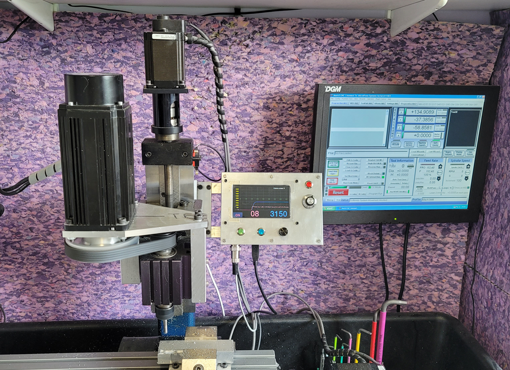
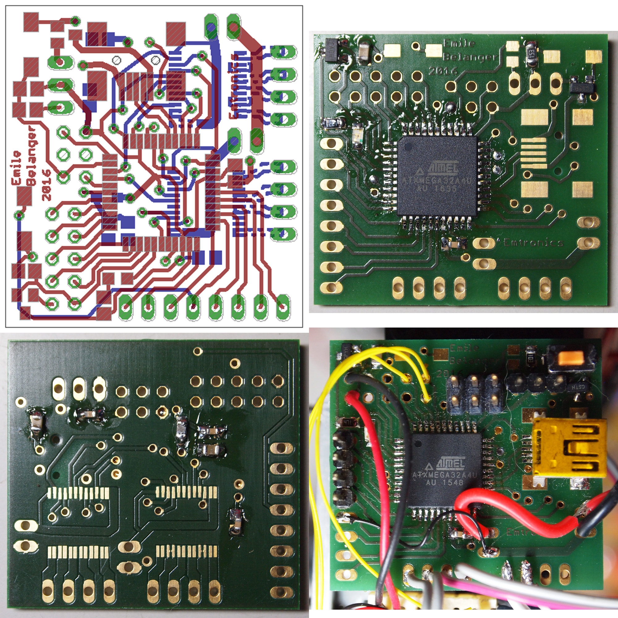
One QuadServo board being used to control 3 custom servo motors Hardware For a robotics project I needed a way of controlling at least 12 motors with analogue feedback to turn then in to servo-motors. I needed a separate board for each of the 4 ‘legs’ of the robot which have 3 motors each. I designed a small PCB (36mm x 33mm) around the Atmel ATXMega32 and 2 x TB6612FNG dual motor drivers. This allows each board to fully control 4 x DC motors and with analogue feedback turn then into servo motors. I added access to the spare pins which were later used to control 8 x RC servos using the standard PWM servo protocol (https://en.wikipedia.org/wiki/Servo_control). I had 8 PCB’s manufactured with PCB-POOL (https://www.pcb-pool.com/), it cost €93. They are certainly not the cheapest but the quality is excellent and I got the boards in a week. Hardware…
Category: Projects
Some electronics projects
Long Music Player for Android
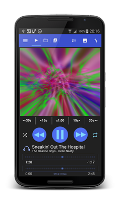
I released a new app – Long Music Player, check it out: http://www.longplayerapp.com/
QuadBot – Android Controlled Robot
Overview Quad Bot is a small robot designed and built from scratch. It has a simple robot arm with 4 degress of freedom, and a small colour camera JPEG camera. It has evolved and is now controlled over Wifi, allowing control with any Android phone. There are 4 independently controlled wheels, allowing maximum control. Below is a system overview. At the heart is a Xilinx Spartan 3 FPGA, using one of the boards I made here. This is programmed with a Microblaze softcore which controls the rest of the system. I have memory mapped Uarts, servo controllers, LEDs etc to the Microblaze. Mechanical Drive The drive consists of 4 independent wheels. Each wheel can be individually controlled – speed, direction and angle. This allows a great degree of movement and robust 4 wheel drive. Also the differential can be implemented electrically rather than mechanically. Parts I used…
Power NZB
My Android app Power NZB was release a few months ago. I’ve just made a new website to host more details, see: www.powernzb.co.uk
Testing realtime PID in Simulink on Hardware
This information was contained in my Quatbot project post, but I have moved it here instead. I decided to test out some PID control of the speed of a wheel in a project I was making. I thought it might be interesting to interface directly with Simulink in Matlab and try and use the provided Toolbox. This allowed the ability to capture data, control speed, and used the Simulink control block ‘live’ in real time with the hardware. So in order to do this I connect the motor and optical sensor to an FPGA, the FPGA then connected via a serial link to the computer. Below show the setup used: Simulink allows the creation of custom blocks called S-functions. I created 2 S-functions, one for reading serial data – this acted as a Simulink source; and the other which wrote serial data – this acted as a Simulink…
Jetpack Joe Android Game
I have finally made a blog for an Android game I have been making for the past few months. I have not been able to spend much time on it recently, but hopefully it may be finished one day! http://www.spacebooty.emtronics.co.uk
Custom Designed and Built Xilinx FPGA boards
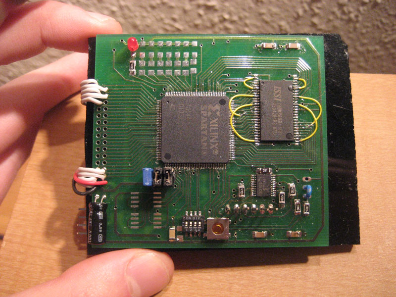
Introduction I designed a small (70mm X 65mm) FPGA board around a Xilinx Spartan 3 FPGA. I decided to make my own for the design experience and it would be cheaper overall than purchasing 4 pre-made boards (excluding time spent of course!). The board contains everything needed to program and run the FPGA + it includes extra memory (SDRAM + EEPROM) and plenty of I/O. Due to the flexibility of the FPGA the boards can be used for many projects. Features The board was designed for the following components: -Spartan 3 XC3S400 -2Mb PROM -16 bit (data size) SDRAM. Up to 256MB (I think) of RAM. Will be populated it 32MB chip. SRAM can also be used with a few mods. 2 X 64KB EEPROM -8 LED’s -4 DIP switch -1 push switch -28 GP I/O -Standard oscillator Design The schematic entry and board design was done using Eagle. Eagle…
Projector Modded With LED
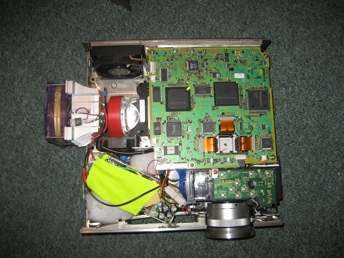
Introduction I got given a Panasonic PT-AE500E projector as it was ‘broken’. As you have probably guessed, the only thing wrong with it was the bulb. Unfortunately the bulbs are ridiculously expensive which meant it was effectivly a write off. So I decided to try and fit a super bright LED instead. I knew it would never be as bright as an original bulb, but it is fine for a dark room. Design Panasonic PT-AE500E projector Athlon XP CPU Heat sink + fan Seoul P7 LED – D-bin (supposedly anyway!..) Seoul P7 star board 2.8A constant current driver 52mm Aspherical Lens Arctic Silver thermal paste (ebay) Lux meter (ebay) I removed the oringal high voltage lamp board, and fit an old Dell 20v power supply into its place – its covered in bright yellow tape in the bottom pics. Results The images above are about 1.5m wide, and the colours…
Testing the HM55b Compass module with an AT90S2313 AVR
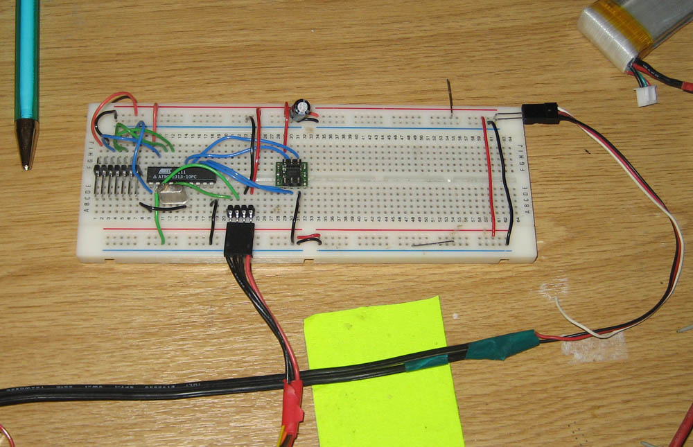
Introduction I received a Parallax HM55B compass module and wanted to quicky test it out, so I interfaced it with an old AVR and wrote a program to read the X and Y values and send them to a PC over the serial port. Design HM55B test video The compass module is wired to PORTB of the AVR, and a USB<->Serial connects to the UART. The software on the AVR is written in assembly. It is programed to wait for a any byte to be recived on the UART, then reads the X and Y values from the HM55B, and transmits them over the UART as 4 bytes – 2 x 16bit signed integers (Y-LSB, Y-MSB, X-LSB, X-MSB). A simple app is written in C# (2008 Express Edition), which requests X&Y, then converts these values into an angle in degrees. Files AVR Studio HM55B test Visual Studio 2008 HM55B test
Jennic Zigbee Module to FT245BM USB
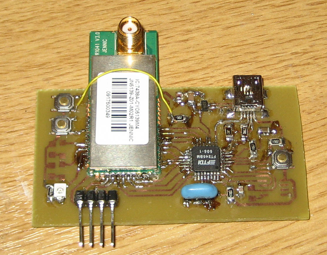
Introduction I built this interface board to allow faster, easier communication to a PC from a Jennic Zigbee module. The FT245BM USB interface chip is wired up in parallel to the IO ports of the Jennic, there is a small driver for the Jennic which allows you to send/get bytes and read status info. Design The board has space for one Jennic module, 3 status LEDs, on board 3.3v regulator and mini USB connector. The board is fully powered from the USB. There is a 4 pin header to access the rs232 for programming. There are two push buttons to allow the module to go into programming mode. I have routed the board so no traces are required on the bottom layer – only a ground plane it needed. This makes it much easier to make the PCB at home as only one side needs to be developed (you still…
Super Bright Bike Helmet Lights
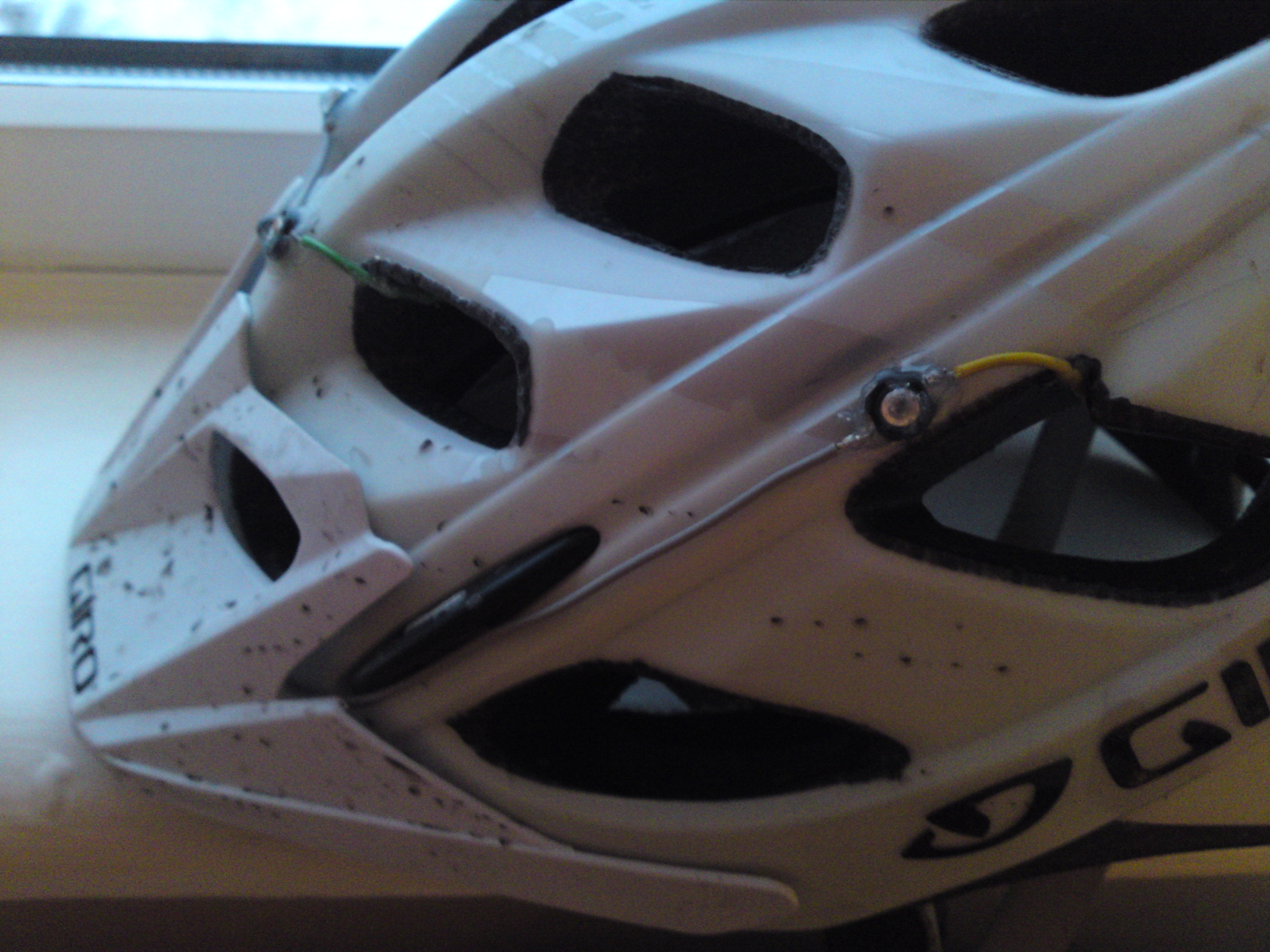
Introduction As I was riding into work during the winter, I wanted to try and reduce my risk of being hit by a car. I decided to make myself very noticeable and different to the drivers, which will hopefully mean they will drive with more care around me.
Compass Belt
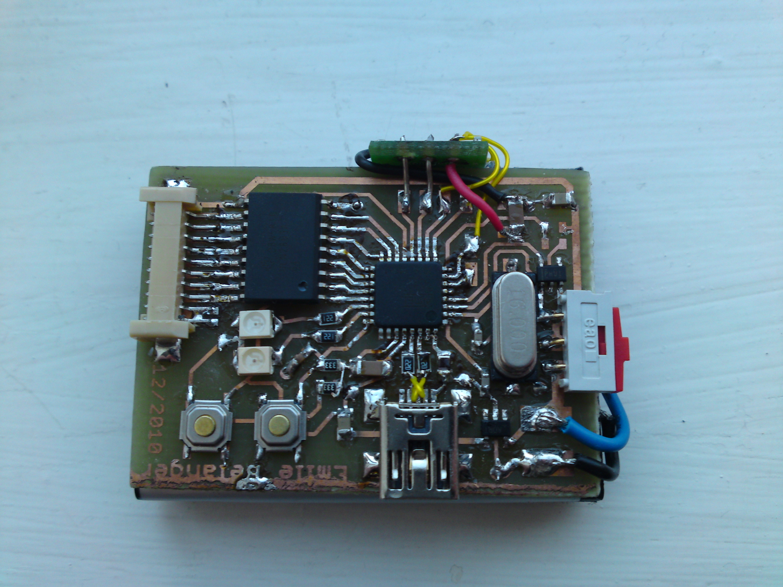
Introduction Last year I saw an article on Engadget on the Haptic Compass Belt, since then I have wanted to make one. Finally a year after having half the components, I decided to design and build one.