
The Taig milling machine comes with a 1/4HP (186 Watts) motor. This motor works great with the machine and I have used it for about a year with not much trouble. However I wanted to upgrade the motor to try and fix a few small annoyances:
* The motor is designed for a 110v 60HZ supply, in the UK we have 240v 50HZ so I need to use a 240v to 110v transformer. This reduces voltage but does not change the supply frequency. This means the motor runs at the wrong speed and does not run optimally. I believe this is why it is quite noisy and also gets EXTREMELY hot (so hot it can not be touch) when being run for a while.
* To change speed you need to move the belt to a different pully. This doesn’t take a particularly long time but it is quite frustrating when it is continually being changed. Every time it is changed there is also a possibility for error (too loose, too tight, unaligned pullies etc) so it adds some risk.

New motor
On ebay I found a 1KW brushless DC motor for £229. It comes with all cables and power control box. 1KW is over powered but it means I can have good power at low speeds.
This is the ebay link (working as of June 2021)
https://www.ebay.co.uk/itm/274036520956?ssPageName=STRK%3AMEBIDX%3AIT&_trksid=p2060353.m1438.l2649

- 1KW maximum power
- Speed: 0 to 2500 RPM
- 4Nm rated torque
- 12Nm max torque
- Speed control
- Position control
- Torque control
- MODBUS RS232/RS485 control interface
Mechanical design
Pullies
I wanted the maximum speed of the spindle to be 10,000RPM, therefore with a maximum motor RPM of 2500 I need at least 4:1 ratio on the pullies. However after looking at the pully sizes it was apparent this ratio is not really feasible without two stages of reduction.
After playing with the motor settings I found I can actually run the motor at 3000 RPM seemingly without any trouble therefore need a 3.3:1 ratio.
In the end I ordered:
60 Tooth HTD5 pully for the motor (https://www.beltingonline.com/pilot-bore-c-272_285_482_493/60-tooth-htd5-pulley-605m15-p-7788.html)
22 Tooth HTD5 pully for the spindle (https://www.beltingonline.com/22-tooth-htd5-pulley-22-5m-15f-7778)
375mm HTD 5mm belt (https://www.beltingonline.com/htd-pitches-c-40_253/5mm-htd-timing-belts-p-4575.html)
The shop also has the option of modifying the bores to the desired size which I opted for (19mm for the motor, 5/8ths for the spindle), and for adding grub screw holes. I could have tried to do it myself but I did not want to risk ruining the pullies for the small amount it costs.
This gives a maximum speed of 8181 RPM, not quite 10,000 but it was good enough. I chose a 22 Tooth pully for the spindle because going lower wasn’t going to leave enough metal when being put on the 5/8th spindle.

Motor mount
I wanted the simplest method of attaching the motor to the block, and I wanted to try and use the existing motor support if possible.

The CAD for the plate was done in Fusion 360. It uses 8mm aluminium and uses the existing motor mount and a new one put on the other side.
In order to reduce noise I put some rubber between the plate and the mounts, this massively decreased the vibrations going through the mill.


The control box is built around a standard aluminium box with a custom face plate


Electronics
Below shows the basic electronics setup.

The servo motor is controlled with a driver unit which can be configured to run the motor in various modes. For this application it is running in ‘velocity’ mode which allows setting from 0 RPM to 3000 RPM. It is possible to configure the various inputs and outputs to have various operations.
I setup the servo driver to allow Modbus comms on the RS232 port, and to enable the motor on the ‘SigIn 1 Input’. While I was trying to debug a grounding issue I also added an input filter to the incoming 240v, I don’t think this is actually needed but I left it on anyway.

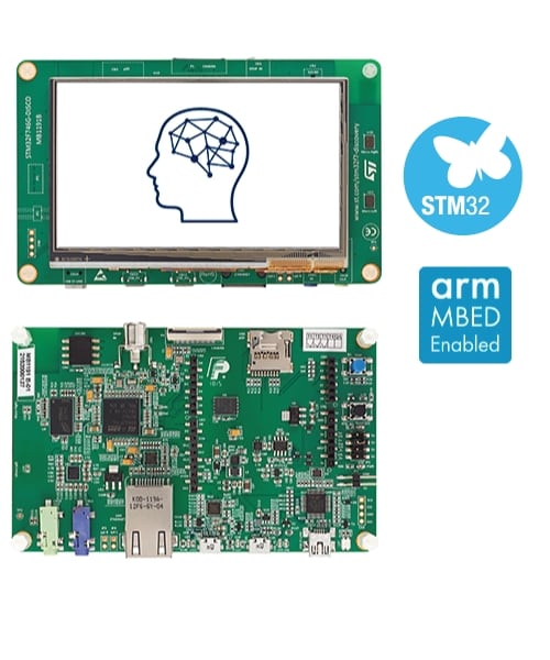
The control box MCU is the 32F746G DISCOVERY from ST (https://www.st.com/en/evaluation-tools/32f746gdiscovery.html). This dev board uses an ARM F7 and comes with a large display.

I needed to add a 5v to 12v DC/DC convertor. This is to drive the SigIn input to the servo driver which needs 12v to operate the opto isolators.

Below shows the back of the face plate. I have not wired up the buttons yet as they are not used.

Below shows the aluminium box. The board in the top left is the RS232 to TTL convertor electronics.

Software
The MCU is responsible for communicating to the servo drive and displaying the graphs on screen. It is running FreeRTOS with 2 tasks, one for comms and one for the display.

The blue line on the graph shows the measured speed in RPM, the red line is the torque in percentage (from none to 100% power).
The source code can be found here: https://github.com/emileb/SpindleControl